Tuesday, 5 April 2011

Wings and Lights

The front cycle wings of the Caterham are supposed to be bolted onto the black wingstay supports on the front hubs. Unfortunately the bolts are a little unsightly, so I chose to glue some cable-tie brackets to the underside of the cycle wings so as to leave the painted upper side smooth. I found some suitable cable tie brackets here: http://www.tlc-direct.co.uk/Products/FXCTB100B.html and I glued them on using a black polyurethane adhesive from Car Builder Solutions: http://www.cbsonline.co.uk/

I fitted the IVA rubber piping around the periphery of the cycle wings and glued this on with ordinary Superglue - seems to work fine. The indicator repeater lamps bolted on OK, and I drilled a hole in the wingstay for a self-tapping screw to hold the ground wire (CC recommends using a rivet, but I prefer something easy to remove!)

The white blobs are Tippex, where I marked the bracket locations

With the front wings securely located, it's on to the rears. First job is to rivet on the nice shiny stone guards, complete with the IVA rubber piping around them. This was reasonably straightforward, but I'm always a bit hesitant when drilling the rivet holes through the nice fresh paintwork!

One of the strange historical quirks of the Caterham is that the left & right stone guards are assymetrical. Originally the left-hand side was cut away to make room for the exhaust, and this has not been changed even for the Duratec models with the exhaust on the right-hand side. So the rear wings end up looking like this:


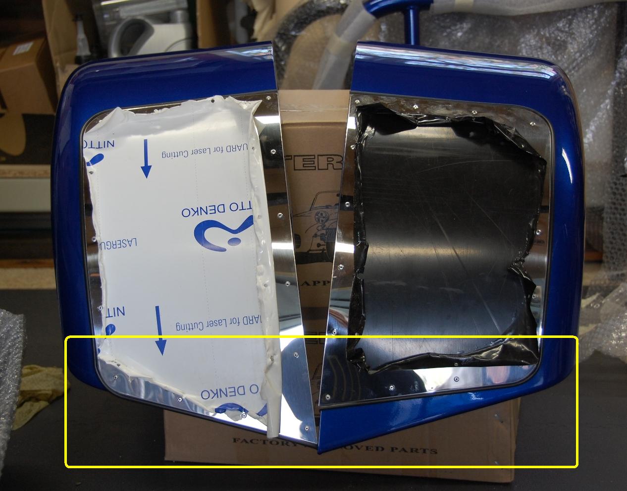
Ignore the protective plastic film on the stainless steel

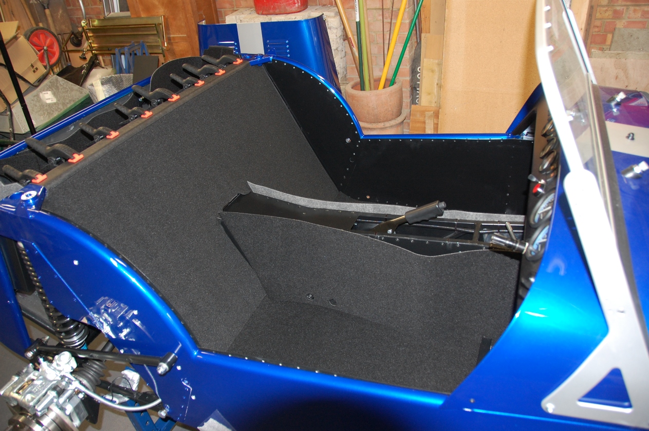
Fitting the rear wings to the body, complete with the thick rubber piping gasket, went OK but I had to file the mounting holes in the wings a little bit to get the bolts to fit through nicely. And whilst I remember, I also had to cut a slot to allow the wings to fit over the already-fitted radius arms.

Three bolts on each wing actually go through into the boot area, so for these I fitted the bolt head from the inside, using a penny washer between the carpet and aluminium body skin, and covered the bolt head with a plastic cap. I think the final results look very nice!


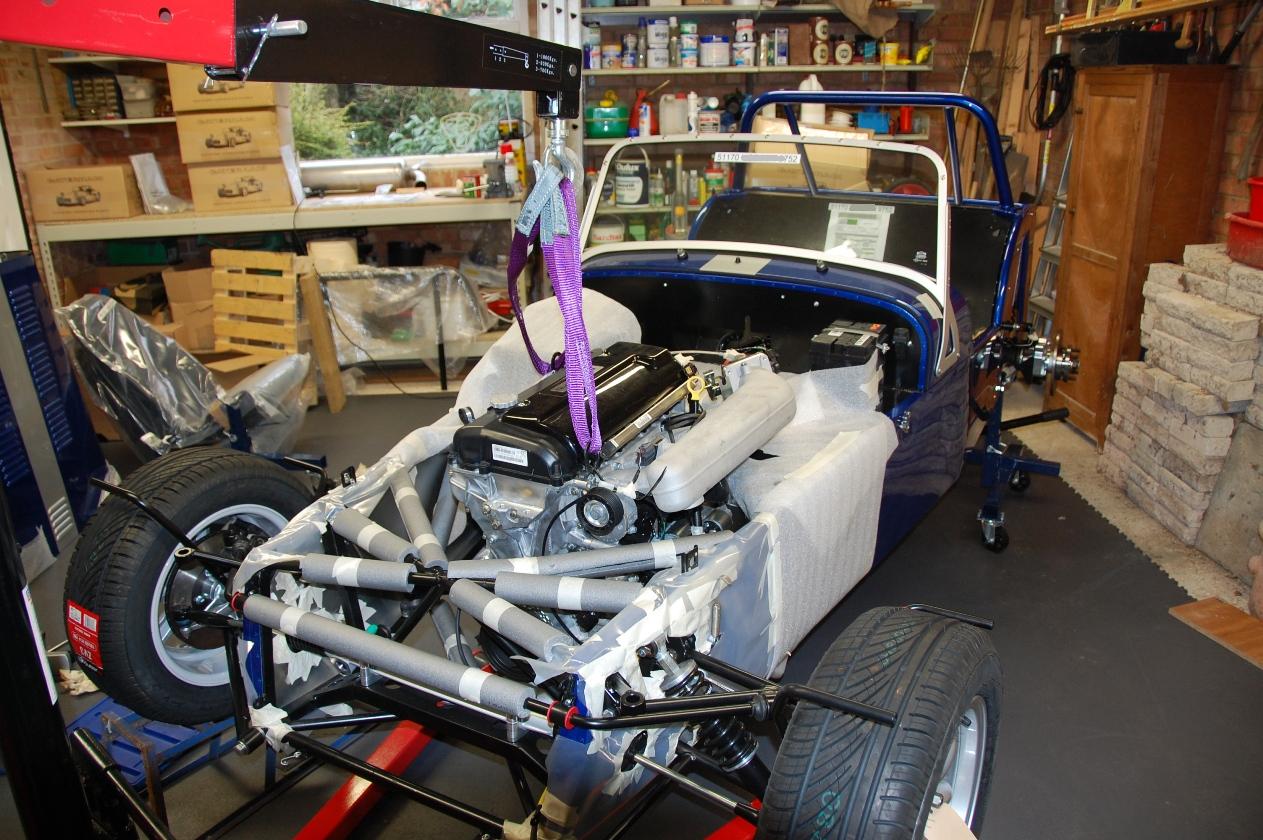
After finishing off the front & rear wings, I thought I'd treat myself to seeing what the car was going to look like "fully clothed", so to speak. So I offered up the nose-cone for the first time, fitted the nose badge, and put the bonnet on. Doesn't this look just brilliant:


Next job was to fit the front and rear lights. On the front, the indicators are housed in black plastic pods which need the rubber IVA piping glued all around (I'm not sure I've done this right, but I hope so...). The main headlamp bolts pass through the indicator pods, and clamp down onto the front suspension bracket. My car has the new "EU4" headlamp brackets, and the cable harness is supposed to pass through the bracket and into the engine bay. This was quite fiddly, and having done some reading on other blogs and the CC IVA guide, I think I may have to do this again - to add grommets to the bracket metalwork, and some extra sleeving to the cable harness. A royal PITA, but I want the car to pass IVA....


The rear lamp clusters were easy, you have to drill mounting holes into the rear wings but CC have made life easier by already drilling one hole in the right place for you. The cable tails are really short on the rear clusters, I had to untie the main harness and move it around a little to give enough length on the left side. I think I need to add some extra sleeving to the cables inside the wheel arch to make sure no bare wires are visible, this is an IVA requirement. Incidentally, this company has all the necessary wiring spares:
http://www.vehicle-wiring-products.eu/

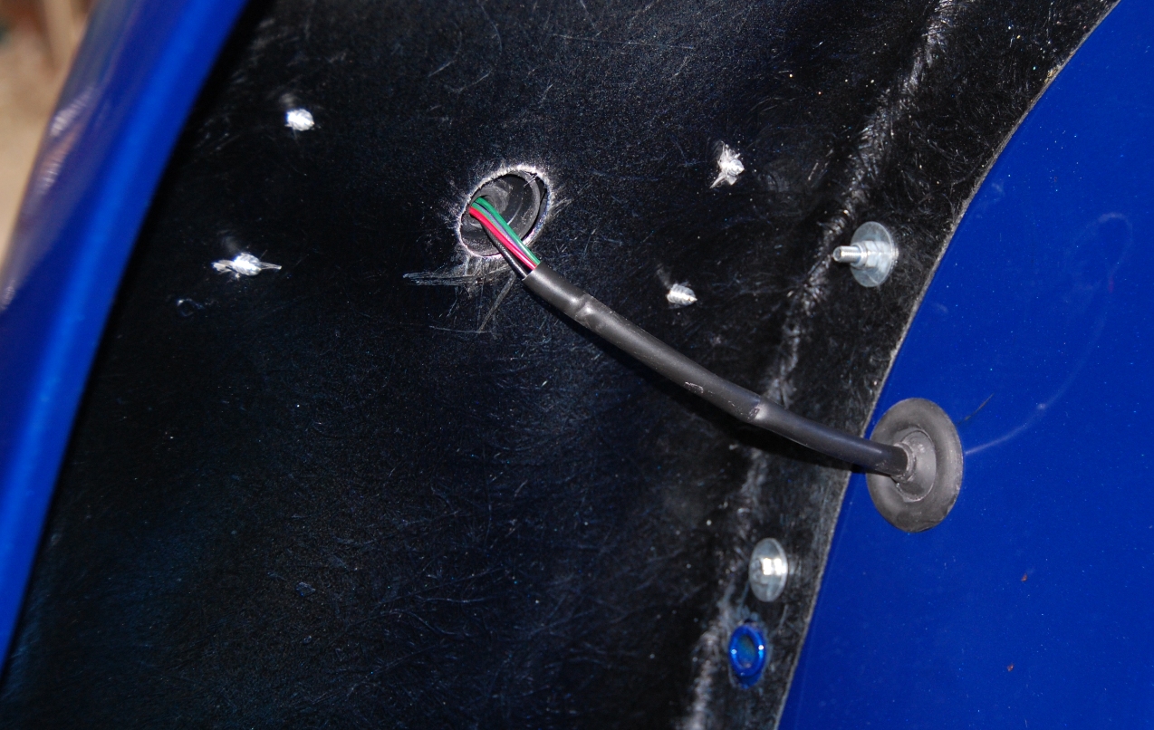
Need some extra sleeving on this cable

To check the lights were wired OK, for the first time I actually connected up the battery, inserted the key and turned on the ignition - Hooray! No smoke! And the lights all work! Phew...

Finally I added a silver vinyl stripe to the rear panel of the car, to match the bonnet. This looks really nice, and for some reason CC do not offer this as a standard option when you order the bonnet stripe. Perhaps because a lot of people have the rear spare tyre option. Whatever.


The car is now booked in at CC for the Post-Build Check, followed by the IVA test in about 5 weeks from now. There's not much more to do; quite a lot of little jobs though (such as the small matter of starting the engine...).

Total build time to date = 125 hours.

Thursday, 24 March 2011

Interior Comfy Bits

This is the part of the job I was least looking forward to: I'm not very good with upholstery and that kind of thing, I can sew a button onto a shirt but that's about the limit of my competence. Anyway - it turned out rather easier than I thought, and I think the results look pretty good. First thing to do was glue the carpet onto the main bulkhead behind the seats. This was straightforward, I used Evo-stik Impact contact adheasive for all the carpet work, mostly using the aerosol spray dispenser. Surplus overspray was wiped off with a rag dipped in white spirit.

Note the spring clamps holding the rear vinyl bit whilst the glue set.

Next, the transmission tunnel carpets are glued down both sides, and the glue is allowed to set for a good while prior to installing the main transmission tunnel "leather" console. This was quite tough, manouevring it over the handbrake and gear levers, then around the main wiring harness at the front scuttle end. A lot of sweat and strain was used to get this located properly, but once in place, it looks first class. Especially with the gear knob in place!


Next I did the carpets in the boot area. This was quite fiddly but the carpet pieces in the kit were all approximately the correct size and shape, so only a little Stanley knife fettling was required. I removed the roll-over bar and the boot floor whilst doing this job, it made things quite a lot easier. In fact, I think I'm going to leave the boot floor out for now, because it looks like this will make the connecting up of the rear wheel arches and lamp clusters somewhat easier.


After the boot carpets, the next job is to install the natty stainless steel "sill protectors" that fit over the driver and passenger side door sills. You push these into place, then drill through the stainless to match up with the rivet holes in the side panel & chassis rails. I bought a couple of new drill bits especially for this - stainless is really tough to get through unless your tools are sharp. After drilling the holes, I fitted the IVA-required rubber piping strip between sill and panel, plus the "knee protector" metal panels that go just under the dash in front of driver and passenger. These panels needed to be bent into shape a little to fit properly. After this, it's out with the rivet gun and pop all the interior panels together including the rear curved bits by the driver/passenger shoulder, which also need rubber piping.

Note the little "escutcheon plate" to hold the door arm-rest clip.

After this, I laid the rubber floor mats and under-seat carpets, which do not require to be glued because they are held in place by the seat runners. I also installed the 12V cigar-lighter socket in a hole I had drilled through the rear bulkhead between the seats - this seems a strange place to put it, but the wiring harness is there in the boot area and it is actually quite convenient even for the cable to a windscreen-mounted GPS. Trust me, I think it will work...

Next I installed the driver and passenger four-point harnesses. This was easy, but I think I will have to remove the top bolts again when I get around to installing the fabric boot cover.

 Just a minute... There's something missing!


 That's better!

The seats went in easily - where the bolts go through the chassis I had to file down the sides of the penny washers, because the strengthening-rail rivets were too close to the seat mounting holes, but aside from that it was simple. Boy, it feels really, really good to sit in the car for the first time! The seats adjust for position OK, I can reach the pedals fine, and it is comfortable! Bloody brilliant.

Brrrrmmm! Brrrrmmm!

Next up is the front & rear wheel arches, and lighting / electrics. Total build hours so far: 100.

Tuesday, 15 March 2011

Diff & Rear Suspension

First job on the rear axle assembly is to get the handbrake installed (!)... This is because it is easier to route the handbrake cables without the diff in the way. The handbrake went in without any problems - I had to wind out the adjuster quite a long way to be able to get the clevis pin to mate up with the handbrake assembly, but otherwise no difficulty. I have wired up the brake microswitch to the connector on the harness, although there is no mention of this in the manual - hope it works!


The next thing to do is insert the propshaft into the transmission tunnel - do it NOW, before the diff goes in! It is not possible to install the propshaft after the diff is fitted.

Diff installation is next. I put the diff on a wooden block on top of the trolley jack and gently raised it into place, this seemed to work quite well (it was too heavy to lift into place manually). The bottom bolts go in quite easily, and it is relatively straightforward to add shims to get the diff centralised left-to-right across the car. The top bolt was a bit more tricky, I had to thump it in with a soft hammer, which made adding shims quite tough! I used sellotape in a ring around the washers to keep them together whilst inserting them between diff & metalised bush.


Having torqued the top bolt, I removed the lower bolts one side at a time and put Loctite on each before re-inserting and torquing up. Final measurement of the diff centrality left-to-right is within 0.5mm.

Next job according to the Guide is installation of brake pipes onto the De Dion tube, but before this I decided to add some rustproofing to the inside of the tube. I squirted Waxoyl as far as I could, from each end, to try and stop the tube rusting if there is any moisture ingress.

Next I put the tube on my workbench and lightly bolted the aluminium hub carriers, caliper brackets and brake calipers to each end. I installed the 3-way brake union onto the tube (the nut was very difficult to tighten, it was getting really hot and I thought I was stripping the thread - but I was definitely using the right size according to the Guide, and it feels OK now). The brake pipes fitted OK but both left & right pipes needed to have the final 10cm bent into a semi-circle in order to locate properly into the brake calipers. I clamped each pipe into a bench vice (with soft jaws!) and hand-bent the pipes using my 41mm hub socket as a former...


Next the De Dion tube is inserted into the chassis, behind the diff. I protected the chassis rails with foam wrap in order to prevent scratches. The rear shocks and radius arms go in next, and these are bolted to the De Dion tube. I'm not going to torque up these bolts until I can put the weight of the car onto the wheels/springs, to make sure the rubber suspension bushes are not twisted under normal loads.


The radius arms stop the top of the De Dion tube from rotating, and the bottom of the tube is held in place by an "A-frame" bracket. The apex of the A is bolted to a central rubber bush on the bottom of the De Dion tube, and the two arms of the A to the suspension bushes in the front of the wheel arch. Installation was straightforward except that the central bush can only be tightened with a very thin socket set (the nut & bolt are recessed into a metal sleeve). Also there are badly-fitting nylon washers either side of the bush, which do not fill me with confidence....


My kit did not include a rear anti-roll bar, so the next job is to build up the remainder of the hub components onto the De Dion tube ends. This starts with inserting the drive shafts into the diff, then locating the aluminium "ears" and the main hub carrier bearing over the ends of the shaft & De Dion tube. These are then bolted in with loctite and torqued up.


After this, the brake discs can be located over the driveshaft ends and the big locknut screwed on (note that the shaft on the left side of the car has a counter-clockwise thread). The nuts are supposed to be done up to 270nm, but I'm just taking up the slack for now until I can lock the wheels properly.

The speed sensor is screwed on to a small bracket on the right-hand-side hub, and adjusted to be 1mm away from the serrated ring on the driveshaft.

Finally the brake calipers and pads can be installed onto a carrier assembly that bolts onto the top of the aluminum hub ears. The brake pipes can now be screwed into the caliper assembly, and the handbrake cables connected.

Ready to roll!

Adjusting the handbrake tension was extremely difficult. The adjuster plastic nut is hard up between the diff and the chassis, and I found it almost impossible to tweak from below. It's much easier from above, but after the interior trim is installed this won't be possible... Hope I don't have to adjust it any more!

Last but not least, I filled the diff with the EP90 oil. I did this from above, using a funnel on a 2ft pipe, having removed the boot floor. Whilst I was there I also painted the wooden bit of the floor with preservative.

Interior is next up....

Tuesday, 8 March 2011

Plumb Crazy

Next job after the engine bay electrics is to install all the cooling hoses and ancillary bits and pieces. This begins with the crankcase breather bottle, the radiator and electric fan, then the primary water reservoir:


This was all quite straightforward. Then came all the hose connections, which was a bit more tricky... trying to decide which hose went where, and cutting them all to the right length, was a bit of a jigsaw puzzle. Thankfully a friend at the Lotus Seven Owners Club forwarded me some photos from Sean at CC, showing how the hoses ought to be routed - this made life much easier, but I still had to be a little creative with the routing of the hoses around the heater area. Firstly these hoses foul on the engine air inlet filter, and secondly routing the hoses down to the oil cooler 'modine' unit was difficult due to the ever-present washer bottle (which seems to get in the way of everything!). Anyway, I think I've got all the waterworks sorted now:


The heater control cable went in OK, and then I went around with a bunch of cable-ties making sure all the hoses were located tightly and not flapping about in the breeze. There was only just enough hose to go around, by the way, and I also had to buy a couple of spare 25mm hose clips.

Final job in the engine bay was to install the throttle cable, which I thought was going to be easy but turned out to be a bit of a pain. Firstly the throttle pedal didn't have a slot in it for the throttle cable to fit through, so I had to get the hacksaw out (always a bit worrying when you start cutting bits off a new car, and you're not quite sure if you are doing it correctly!). Secondly the throttle cable seemed to be a couple of inches too long to be able to adjust correctly. Scratched my head for a while over this one, until I noticed that pedal mounting bush had been bolted on the wrong hole (there are two possible threaded holes in the footwell!). Anyway when I changed to the alternate mounting hole everything lined up OK and I could adjust the cable tension correctly to get the full range of motion on the inlet diaphragm.

Job's a good 'un!

Next thing in the manual is to actually fill up with anti-freeze mixture, but I think I'll leave that until later on in the build process, and move onto the rear suspension.

Total work hours so far: 55

Thursday, 3 March 2011

Engine Bay Ancillaries

After the engine install, then comes the big connecting-up operation! Actually the first thing I had to do was move the washer bottle bracket over an inch - the factory had put the bracket in a location where the bottle fouled on the starter motor. Doh! After drilling out the rivets, I re-fitted the bracket in a better place. Then I set about fixing up the various electrical connections to the engine: ECU, MFU, sensors, etc. The MFU had to be fixed to a bracket rivetted to the battery tray/holder strap, which is stainless steel and was bloody difficult to drill through...


I've bolted the battery cables & earth straps in places where I think it makes sense, I guess I'll know if this is good enough when I try and start the engine! There's still a couple of loose wires yet to connect up - water temp sensor, rad fans etc., these will be done in due course.

Next I bolted the exhaust pipes on, after removing the sticky paper labels (to avoid the disturbing burning smells when the engine is first started!). This was a fairly straightforward process, note that it is very important to protect the bodywork orifice with card or foam to avoid scratching. The first 3 pipes went in OK from outside-to-inside, but the 4th pipe I could only locate by manouevring it from inside-to-outside. The collector/cat unit slipped on easily, then I supported it's weight whilst tightening up the pipes on the exhaust gasket and making sure there was even space around the pipes and bodywork hole. Finally the 2 spring units were coaxed on, holding the cat unit to the pipes. Point to remember - the hooks on the pipe & cat need to be "knocked in" after fitting the springs, for IVA purposes (according to the Caterham guide).


I'll put the silencer box and the heat shields on when I've done the rear wheel arches.

Next the gear lever and reversing switch went in. I have to say that I felt a bit of a tingle when first moving the gear lever around in the gate - I'm so looking forward to doing this many times in the future!


Finally for this section, I installed the steering column and wheel. This was not really feasible before the engine went in, and in fact I'm glad that I waited until after fitting the exhaust pipes as well. It would have been very tough fitting the pipes with the column in the way.

The lower column and UJ goes in first, then the upper column and joining bracket. The upper column was tough: The rubber & plastic bushes are tight in the column surrounding tube, and it is easy to knock them out of place if you are not careful. Also, I belatedly realised that my quick-release Momo wheel only goes on at a specific rotation angle - you need to line up the steering straight forward, with the lump on the column splines in exactly the right place. I had to re-adjust the lower column UJ spline bolts a couple of times to get this spot on. The wheel looks really good in situ. This bag of bolts is beginning to look like a car!


Next week I will move on to the plumbing & heating...

Tuesday, 22 February 2011

Engine Installation

The first thing to acquire before starting the engine install procedure is a suitable hydraulic hoist and sling. I managed to get hold of a Sealey PH10 crane and 1 tonne / 2 metre sling, and this worked out perfectly.


The engine install is definitely a 2-person job (minimum!), and I was ably assisted in this task by my mate Bob. First thing we did was to lift up the engine to the appropriate height and offer it up to the front of the car. It immediately became apparent that the legs of the crane would foul the axle stands supporting the chassis, so we decided to simply put on the two front wheels and raise them up on wheel ramps. This gave ample space for the crane.

My assistant Beaker (sorry Bob)

Manoeuvring the engine into place and dropping it down into the bay was actually a lot easier than we had expected - the most difficult part was making sure the tail end of the gearbox fitted in above its support bracket on the chassis. We used the trolley jack underneath the car, to support the back end of the gearbox at the correct height as we dropped the front of the engine down. Almost no fouling of parts occurred: only the washer bottle had to be taken off, plus an alternator bolt that I had mistakenly left in situ.

It's in!

The most difficult part of the whole operation turned out to be the fitting of the various engine mounting bolts. Taking the weight of the engine on the crane, we first loosely bolted on the two main engine mounting struts and checked alignment with the rubber chassis bushes. It looked OK, so I tried to put in the right-hand-side long mounting bolt. This promptly cross-threaded, because the engine was actually canted over slightly. It was very tricky to get the engine at the correct angle with the bolt also lined up on the bush, so what we ended up doing was removing both the mounting strut and the rubber bush from the chassis, bolting them together off the car, and installing them as a pair using the slack in their own long bolts to line it up. This was a lot easier. The rear two bolts on the gearbox mount went in fairly readily, and we lined up the gearbox by eye centrally in the transmission tunnel before tightening up.

Total time for the engine install was a shade over two hours - very pleased with that. Off to the pub for a pie and a pint (or a burger and several pints, to be more exact).

Friday, 4 February 2011

Gearbox & Engine Prep

First, the gearbox needs to be bolted to the bell-housing & engine. The bell-housing was delivered already bolted to the engine, with the gearbox as a separate unit (NB. I ordered a regular 5-speed box). So, first job was to unbolt the bell-housing from the engine, connect to the gearbox, and re-bolt to the engine. No problem.


Don't forget to check the clutch release bearing hydraulic pipe connection is tight before re-fitting the bell-housing to the engine! You don't want to have to remedy this later...

Now - moving on to the engine installation. With the Ford Duratec 2 litre engine, you are supposed to use the R400 chapter in the Caterham Assembly Guide. This chapter is roughly accurate, but contains many "ambiguities"....

There's quite a lot of ancillary bits & pieces to get sorted out before the actual engine install. First off, the windscreen washer bottle and pump needs to go in (all mod-cons in the Caterham!). The metal mounting bracket for the bottle was already installed by CC in my engine bay (excellent! I wasn't expecting that...) but I had to route the water pipe from the pump to the windscreen jet. No problem here, except negotiating the pipe through the wiring loom grommet in the transmission tunnel, which was a bit fiddly.


Next, the manual says you have to connect the water rail and L-shaped rubber hose to the engine. I couldn't find either of these items in my kit, so a quick email to Sean confirmed that they have changed the design and these parts are not necessary. I proceeded onto the rubber engine mounts....


Note that it is important to scrape off the black paint on the LH mount, which also contains the engine electrical ground strap. After the engine is installed and this bolt is tightened, I will cover it in copper grease to try and prevent corrosion on an important electrical contact.

Horns go in next, and I used a couple of large penny-washers on the brackets because the holes were a little too large to just bolt down.


Next job is to protect as much of the engine bay as possible with padding, in order to avoid scratches and dents when the lump is shoe-horned in. I used a mixture of 15mm pipe insulation and 2.5mm foam packing wrap.


Last but not least, I removed from the engine all the items which I thought would get in the way during the install: The two main mounting brackets, and the alternator & belt. The guide says you should remove the starter motor as well, but having read a lot of other people's build diaries this does not seem to be necessary.


Now: all that is missing is my drinking pals, who have kindly offered to lend a hand with the engine installation (in exchange for sundry beverages).

Total build time so far: 25 hours